 Cat5eイーサネットケーブル
 CAT6イーサネットケーブル
 Cat6aイーサネットケーブル
 Cat8ケーブル
 バルクイーサネットケーブル
 コネクター&ジャック
 ケーブル管理
 ネットワークツールとテストツール
 OS2 シングルモード単信
 OS2 シングルモード二重
 OM3マルチモードファイバー
 OM4マルチモード
 OM2マルチモード
 OM5マルチモード
 MTP/MPOケーブル
 パッチケーブル カスタム
 光ファイバ部品
 クリーナー&ツール
 DisplayPortケーブル
 ミニDisplayPortケーブル
 HDMIケーブル
 HDMIミニ/マイクロケーブル
 DVIケーブル
 VGAケーブル
 オーディオケーブル
 Thunderboltケーブル
 USB-Cケーブル
 USB 3.0ケーブル
 電源ケーブル
 SATAケーブル
 シリアルケーブル
お買い物カゴに商品がありません。
SOP TEST — USB Cable Types
USB Connectors
The connectors the USB committee specifies support a number of USB's underlying goals, and reflect lessons learned from the many connectors the computer industry has used. The connector mounted on the host or device is called the receptacle, and the connector attached to the cable is called the plug.
The designation C (Type-C or USB-C) refers only to the connector's physical configuration, or form factor, not to be confused with a cable or port's specific capabilities and performance, such as Thunderbolt 3, DisplayPort 2.0, or USB 3.2 Gen 2×2. While USB‑C is the single modern connector for all USB protocols, there are valid uses of the connector that do not involve any USB protocol. Depending on the protocols supported by all connected devices – host, intermediate devices (hubs), and peripheral devices – a USB‑C connection can provide much higher data rates and electrical power than anything using the superseded connectors.
A device with a Type‑C connector does not necessarily implement any USB transfer protocol, USB Power Delivery, or any of the Alternate Modes: the Type‑C connector is common to several technologies while mandating only a few of them.
USB-A and USB-B Connectors
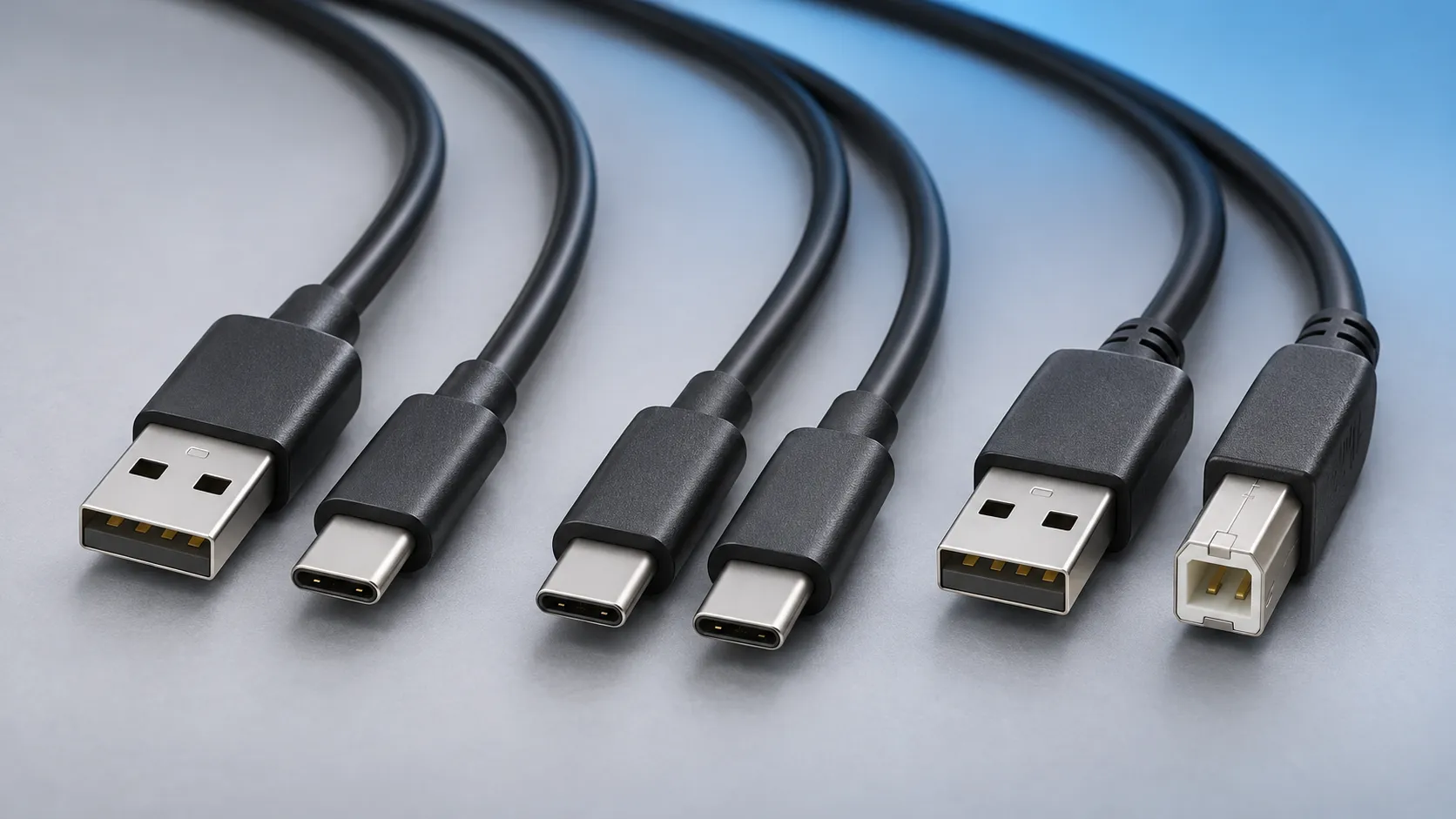
USB-A female is the standard "host" connector type. This is found on computers, hubs, or any device intended to have peripherals plugged into it. It is also possible to find extension cables with a female A connector and a male A connector on the other end.
USB-B female is a standard for peripheral devices. It's bulky, but robust, so in applications where size is not an issue, it's the preferred means for providing a removable connector for USB connectivity. It is usually a through-hole board mount connector, for maximum reliability, but there are panel-mount options for it as well.
USB-B male is almost exclusively found at the end of a cable. USB-B cables are ubiquitous and inexpensive, which also contributes to the popularity of the USB-B connection.
Mini and Micro Connectors
Mini-USB connectors were introduced together with USB 2.0 in April 2000, mostly used with smaller devices such as digital cameras, smartphones, and tablet computers. Both Mini-A and Mini-B plugs are approximately 3 by 7 mm (0.12 by 0.28 in).
The thinner Micro-USB connectors were intended to replace the Mini connectors in devices manufactured from May 2007 through late 2014, including smartphones, personal digital assistants, and cameras.
USB-Micro male is also a cable-only connector. There are generally two types of cables with USB-Micro male ends: one for connecting a device with a USB-Micro port as a peripheral to a USB host device and one for adapting the USB-Micro female port to a USB-A female port, to be used in USB-OTG capable devices.
USB 3.0 micro-B cables look similar to USB 2.0 micro-B connectors but they include additional pins for two differential pairs and a ground.
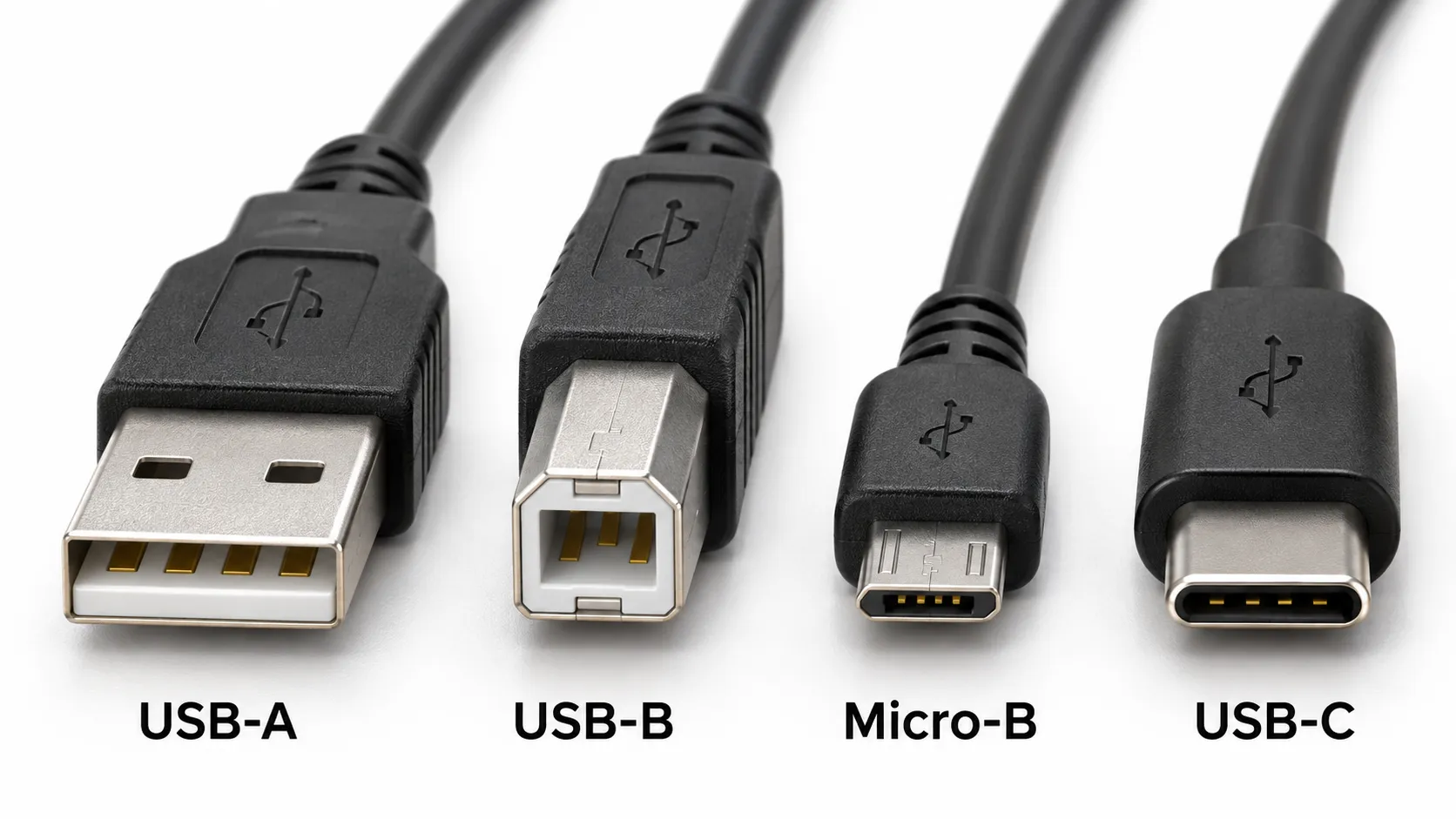
USB-C Connectors
The USB Type‑C connector has 24 pins and is reversible. The designation C distinguishes it from the various USB connectors it replaced, all termed either Type‑A or Type‑B. Whereas every earlier valid USB cable had a host end A and a peripheral device end B, a USB‑C cable connects either way (and the devices handle the logical A–B distinction). For interoperation with older equipment, there are Type-C-to-legacy cables; such a cable has a Type‑C plug at one end and either a Type‑A (host) or a Type‑B (peripheral device) plug at the other.
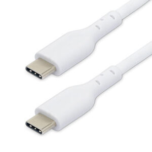
The USB‑C standard simplifies usage by specifying cables having identical plugs on both ends; orientation is moot. Also, the plugs are flat but can be inserted in either orientation.
Cables and Data Rates
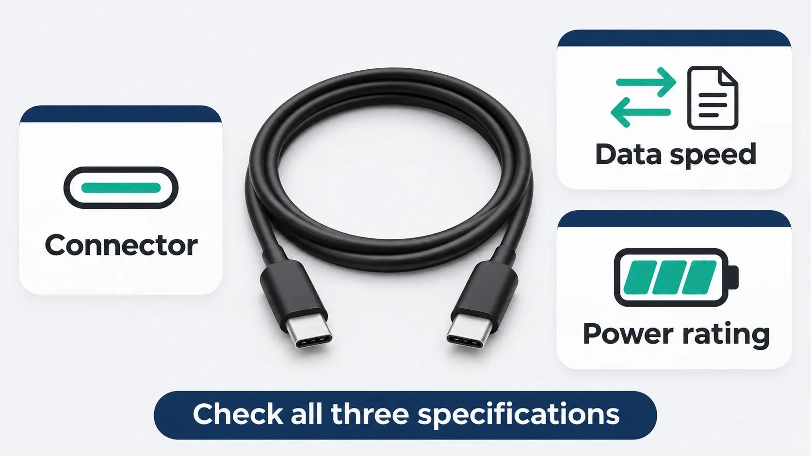
Type‑C cables can be split among various categories and subcategories. The first one is USB 2.0 vs Full-Featured. USB 2.0 Type‑C cables have very limited wires and are only good for USB 1 and USB 2 communications and Power Delivery. They are also called charging cables colloquially. Conversely, Full-Featured cables need to have all wires populated and in general support Alternate Modes and are further distinguished by their speed ratings.
Full-Featured cables exist in different speed grades. Their technical names, the operation modes, use the Gen x notation, each higher number expressing increasing capabilities in terms of data rate. The marketing names are based on the nominal data rates: "USB 5Gbps", "USB 10Gbps", "USB 20Gbps", "USB 40Gbps", and so on. Full-Featured cables can support at least USB 3.x, USB Power Delivery and DisplayPort.
USB 3.2, released in September 2017, fully replaced the USB 3.1 (and therefore also USB 3.0) specifications. It preserves the former USB 3.1 SuperSpeed and SuperSpeedPlus architectures and protocols, with transfer rates of 5 and 10 Gbit/s, and introduces two two-lane operational modes with the same signalling rates in each lane, doubling the transfer rates to 10 and 20 Gbit/s. These are only applicable with Full-Featured USB‑C cables and hosts, hubs, and peripheral devices that use them.
USB4 specification, released in 2019, is the first USB protocol standard that is applicable exclusively via USB‑C.
Power Delivery
Every USB‑C cable must support at least three amps of current and up to 20 volts, for up to 60 watts of power, according to the USB Power Delivery (PD) specification. Cables were also allowed to support up to 5 A while retaining the 20 V limit, allowing up to 100 W of power; however, the 20 V limit for 5 A cables has been deprecated in favor of 48 V. The combination of higher voltage support and 5 A current support is called Extended Power Range (EPR) and allows for up to 240 W (48 V × 5 A) of power according to the USB PD specification.
Each Type‑C cable except the most basic, supporting only up to USB 2.0 and 60 W (20 V × 3 A), must contain electronics, called an eMarker in the standard, that identify the cable and its capabilities via the USB CC protocol. This identification data includes information about product and vendor, cable connectors, supported USB signalling protocols (USB 2.0, USB 3.x, etc), passive vs active construction, use of VCONN power, available VBUS voltages and currents, latency, transmit vs receive directionality, SOP controller mode, and hardware and firmware versions. It also can include further vendor-defined messages (VDM) that detail support for Alternate Modes or vendor-specific functionality outside of the USB standards.
Hosts and Peripheral Devices
For any two pieces of equipment connecting over USB, one is a host (with a downstream-facing port, DFP) and the other is a peripheral device (with an upstream-facing port, UFP). Some products, such as some mobile phones, can take either role, whichever is opposite that of the connected equipment. Such equipment is said to have Dual-Role-Data (DRD) capability, which was known as USB On-The-Go in earlier specifications. With USB‑C, when two such devices are connected, the roles are first randomly assigned, but a swap can be commanded from either end, although there are optional path and role detection methods that would allow equipment to select a preference for a specific role. Furthermore, Dual-Role equipment that implements USB Power Delivery may swap data and power roles independently using the Data Role Swap and Power Role Swap processes. This allows for charge-through hub and docking station applications such as a portable computer acting as a host to connect to peripherals but being powered by the dock, or a computer being powered by a display, through a single USB‑C cable.
Connector Fit and Durability
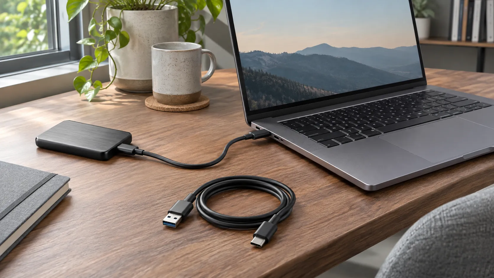
By design, it is difficult to insert a USB plug into its receptacle incorrectly. The USB specification requires that the cable plug and receptacle be marked so the user can recognize the proper orientation. The USB‑C plug, however, is reversible. USB cables and small USB devices are held in place by the gripping force from the receptacle, with no screws, clips, or thumb-turns as other connectors use.
The USB standards specify dimensions and tolerances for connectors, to prevent physical incompatibilities, including maximum dimensions of plug bodies and minimum clear spaces around receptacles so that adjacent ports are not blocked.
Contact – Contacts are the business portion of the connector. They are the metal parts which touch each other, forming an electrical connection. This is also where problems occur: the contacts can become soiled or oxidized, or the springiness required to hold the contacts together may fade with time.
Mating cycles – Connectors have a finite life, and connecting and disconnecting them is what wears them out. Datasheets usually present that information in terms of mating cycles, and it varies widely from one technology to another. A USB connector may have a lifetime in the thousands or tens of thousands of cycles, while a board-to-board connector designed for use inside of consumer electronics may be limited to tens of cycles. It's important that you select a connector with a suitable life for the application.
関連商品
-

1m/2m USB-Cケーブル、USB 5Gbps、60W (3A) パワーデリバリー、4K 60Hz DP Altモード、TPEジャケット - Thunderbolt対応
価格帯: ¥9.99 – ¥13.99 この商品には複数のバリエーションがあります。 オプションは商品ページから選択できます -
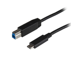
1m USB-B - USB-C ケーブル、USB 10Gbps、データ・コード、USB 3.2 Gen 2、USB-C データ転送ケーブル
¥1,793 -
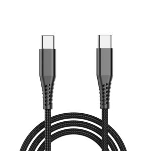
USB-C充電ケーブル、60W(3A)PD、二重編組ナイロン/TPEジャケット、頑丈なUSB C充電コード、USB 2.0ノートPC充電ケーブル
¥2,092 -
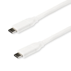
2m/4m USB-C Fast Charging Cable, Charge & Sync, 100W (5A) PD, USB 2.0, USB-IF Certified – White USB C Charging Cord
価格帯: ¥9.99 – ¥10.99 この商品には複数のバリエーションがあります。 オプションは商品ページから選択できます -
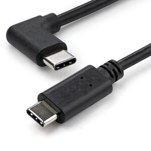
1m USB-C充電ケーブル、右アングル、充電&同期、60W(3A)PD、USB 2.0ノートPC充電ケーブル - USB C充電コード
¥1,494 -
0.5m/1m/2m USB-C - Micro USB-B ケーブル、データケーブル、USB 2.0、USB C - Micro-B データ転送ケーブル
価格帯: ¥6.99 – ¥8.99 この商品には複数のバリエーションがあります。 オプションは商品ページから選択できます -
1m/1.8m/3m USB-C Charging Cable, Charge & Sync, 60W (3A) PD, USB 2.0 Laptop Charger Cable, TPE Jacket – White USB C Charging Cord
価格帯: ¥4.99 – ¥6.99 この商品には複数のバリエーションがあります。 オプションは商品ページから選択できます -
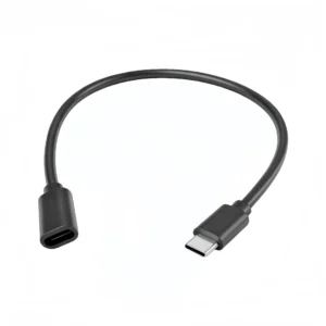
USB‑C オス-メス延長ケーブル Type‑C 延長コード、ハブ・カードリーダー・USB‑C 対応デバイス向け OTG 対応
価格帯: ¥2.01 – ¥5.89 この商品には複数のバリエーションがあります。 オプションは商品ページから選択できます